Projector repair - Sony HW65ES
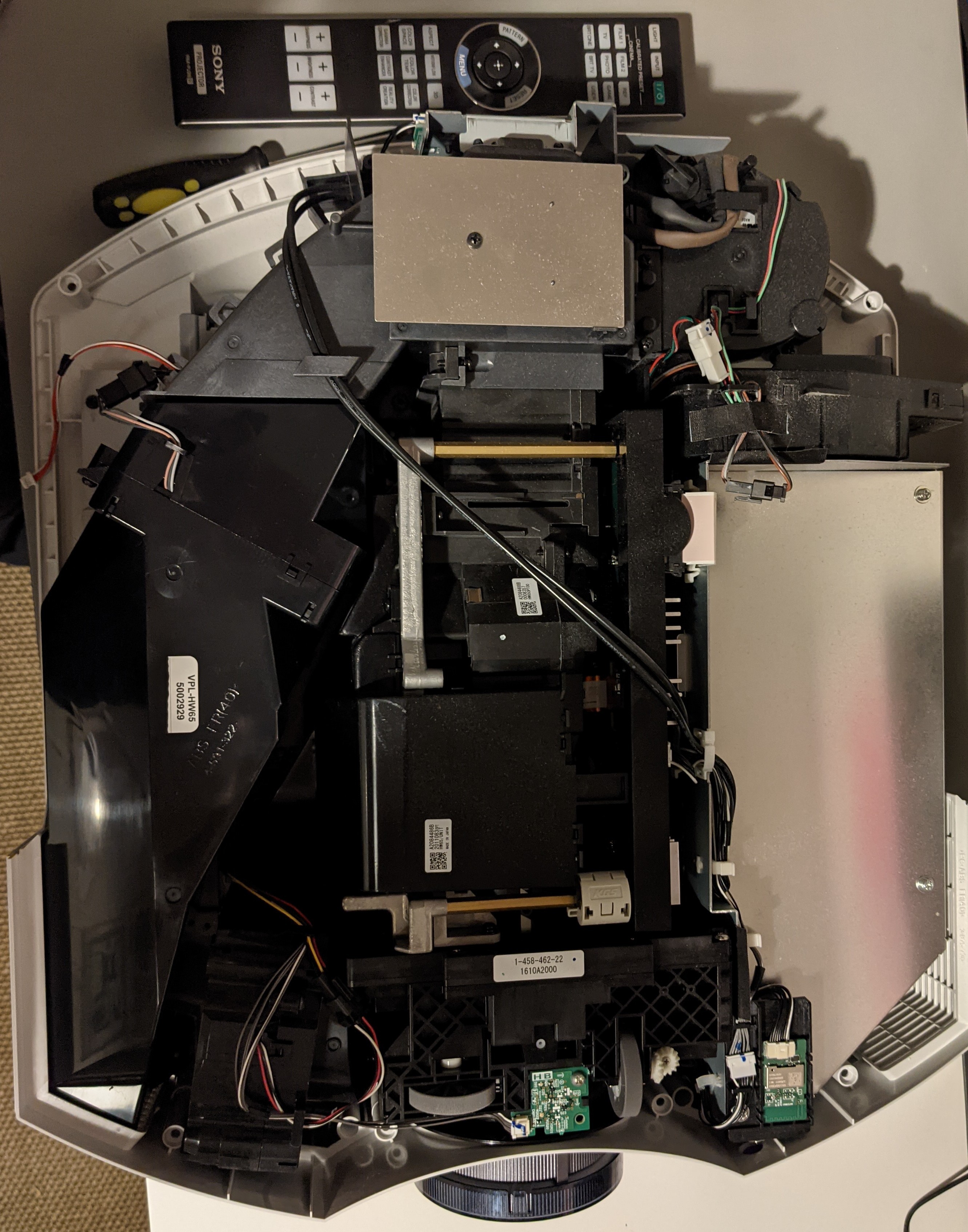
Summer 2021: Lightning strikes... Projector boots up but the HDMI inputs are dead. The repair shop confirms that the QA board is dead. New board costs ~500 EUR, but it is not possible to buy it separately. Repair shop wants ~1800 EUR to fix the problem, which is higher than the market price. A perfect project!
Sony VPL-HW65ES
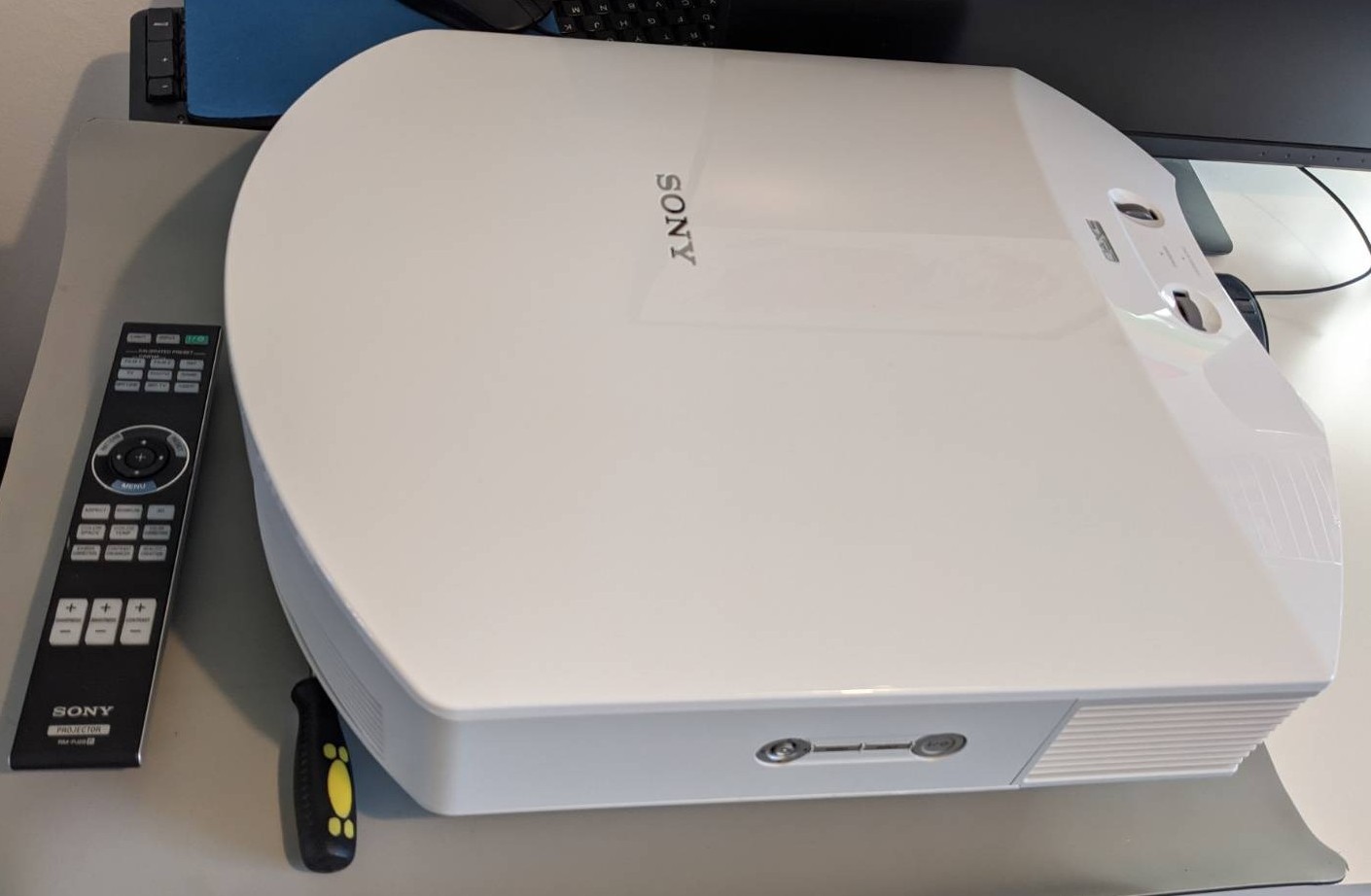
Two HDMI ports and no analogue inputs :-(
Initial Failure analysis
The first thing that I noticed was that the HDMI ports did not work the same way, HDMI2 did respond with a correct EDID, whereas HDMI1 did not.
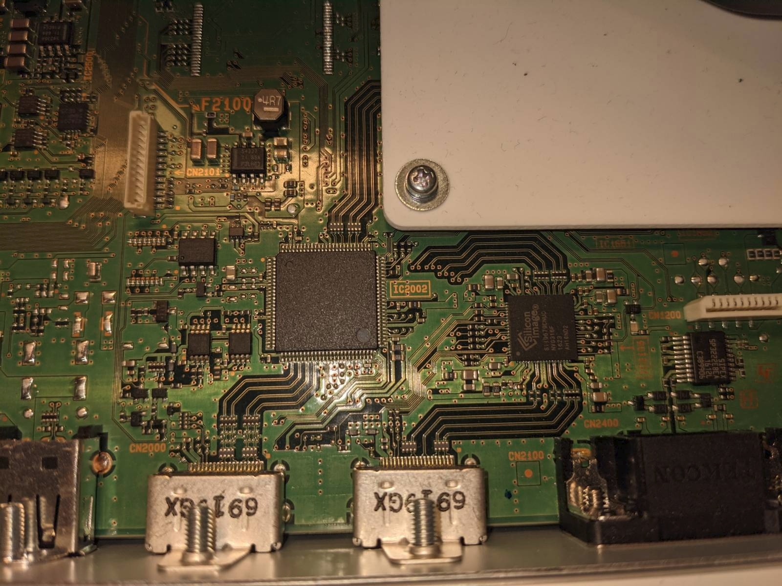 The HDMI related part of the PCB
At first I focused on the ESD protection part of the PCB, see picture below. I could not see any problem there, so I had to look elsewhere.
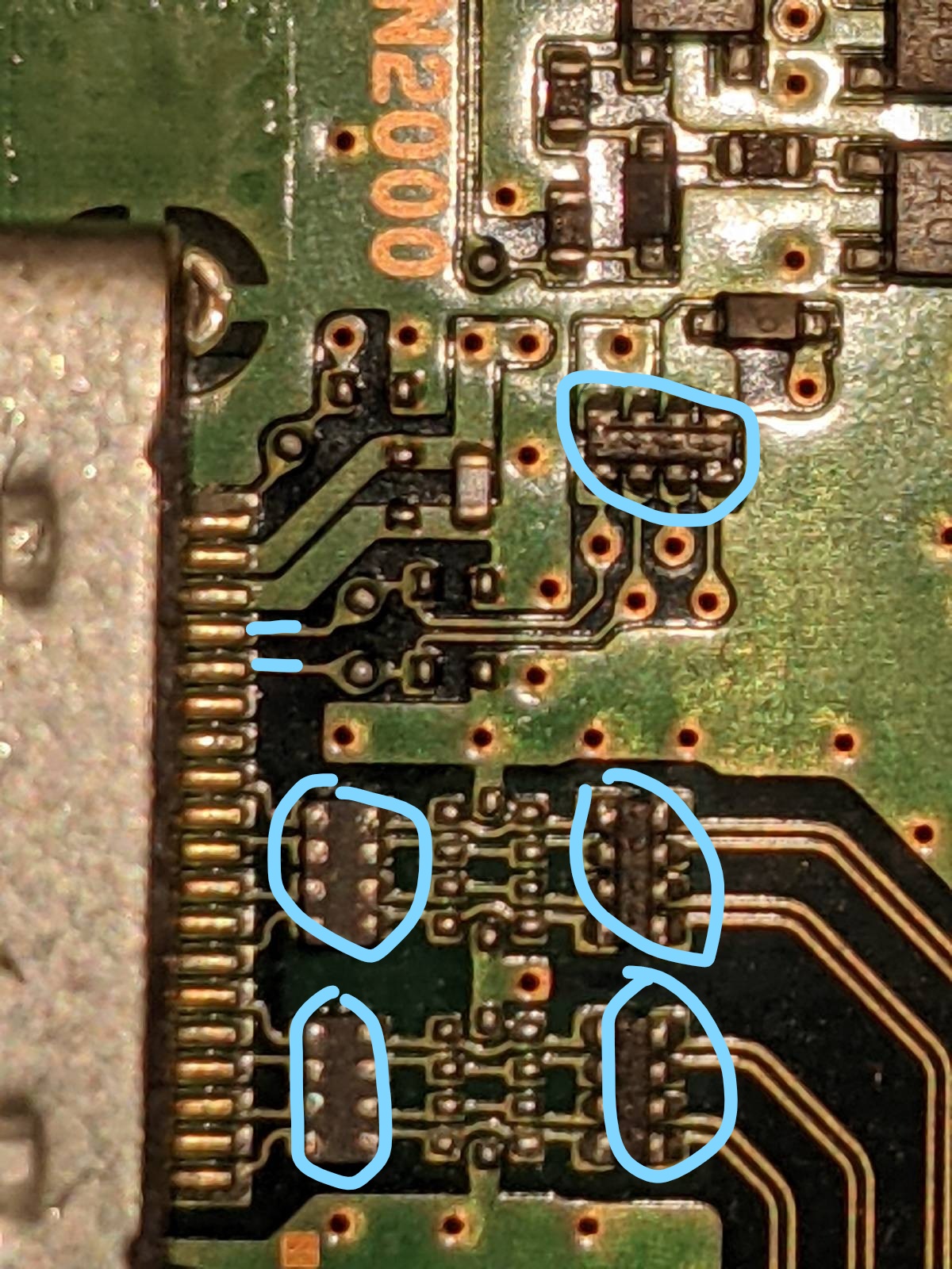 ESD-protection
Measure DDC pins
Are both HDMI ports dead?
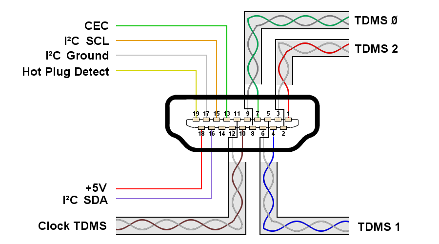 HDMI Connector Pinout, Charly Whisky, CC BY-SA 4.0 https://creativecommons.org/licenses/by-sa/4.0, via Wikimedia Commons
| Port | Pin | Reference | Result |
|---|---|---|---|
| HDMI1 | 15 | GND | Short-circuit (0 ohms) |
| HDMI1 | 16 | GND | Short-circuit (0 ohms) |
| HDMI2 | 15 | GND | Reasonable value (not 0 ohms) |
| HDMI2 | 16 | GND | Reasonable value (not 0 ohms) |
Conclusion: HDMI1 DDC is dead. HDMI2 shows some signs of life!
- 2021-12-01: Using read-edid it is confirmed that HDMI1 is completely dead, but HDMI2 does respond with a proper EDID:
HDMI-2 connected 1920x1080+0+0 (normal left inverted right x axis y axis) 2210mm x 1250mm
        EDID:
                00ffffffffffff004dd903de01010101
                0019010380dd7d780a9955ae5149b224
                0d505421080090408180814001010101
                010101010101023a801871382d40582c
                450000000000001e0e1f008051001e30
                4080370000000000001c000000fd0017
                3f0f440f000a202020202020000000fc
                00534f4e5920504a0a202020202001a7
                02032bb04a101f200514041303120174
                030c002000b82de035ff35ffc8060140
                006790a0e3050301e200fb023a80d072
                382d40102c458000000000001e011d80
                18711c1620582c250000000000009e8c
                0ad08a20e02d10103e96000000000000
                188c0ad090204031200c405500000000
                000018000000000000000000000000f7
        Content Protection: Undesired
                supported: Undesired, Desired, Enabled
        max bpc: 12
                range: (8, 12)
        content type: No Data
                supported: No Data, Graphics, Photo, Cinema, Game
        Colorspace: Default
                supported: Default, SMPTE_170M_YCC, BT709_YCC, XVYCC_601, XVYCC_709, SYCC_601, opYCC_601, opRGB, BT2020_CYCC, BT2020_RGB, BT2020_YCC, DCI-P3_RGB_D65, DCI-P3_RGB_Theater
        aspect ratio: Automatic
                supported: Automatic, 4:3, 16:9
        Broadcast RGB: Automatic
                supported: Automatic, Full, Limited 16:235
        audio: auto
                supported: force-dvi, off, auto, on
        link-status: Good
                supported: Good, Bad
        CONNECTOR_ID: 116
                supported: 116
        non-desktop: 0
                range: (0, 1)
   1920x1080     60.00*+  50.00    59.94    24.00    23.98
   1920x1080i    60.00    50.00    59.94
   1400x1050     59.95
   1280x1024     60.02
   1280x960      60.00
   1280x768      59.87
   1280x720      60.00    50.00    59.94
   1024x768      60.00
   800x600       60.32
   720x576       50.00
   720x480       60.00    59.94
   640x480       60.00    59.94
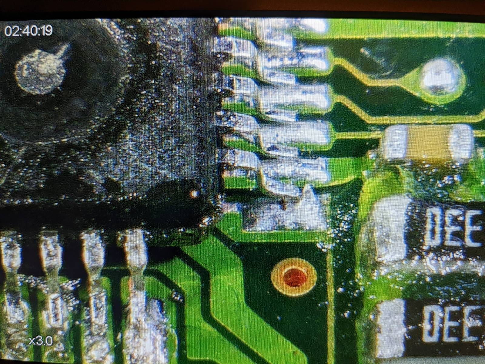
Further investigation showed that PIN 15 (HDMI1) was connected to PIN 50 (DSCL4) on the IC Sil9589CTU0.
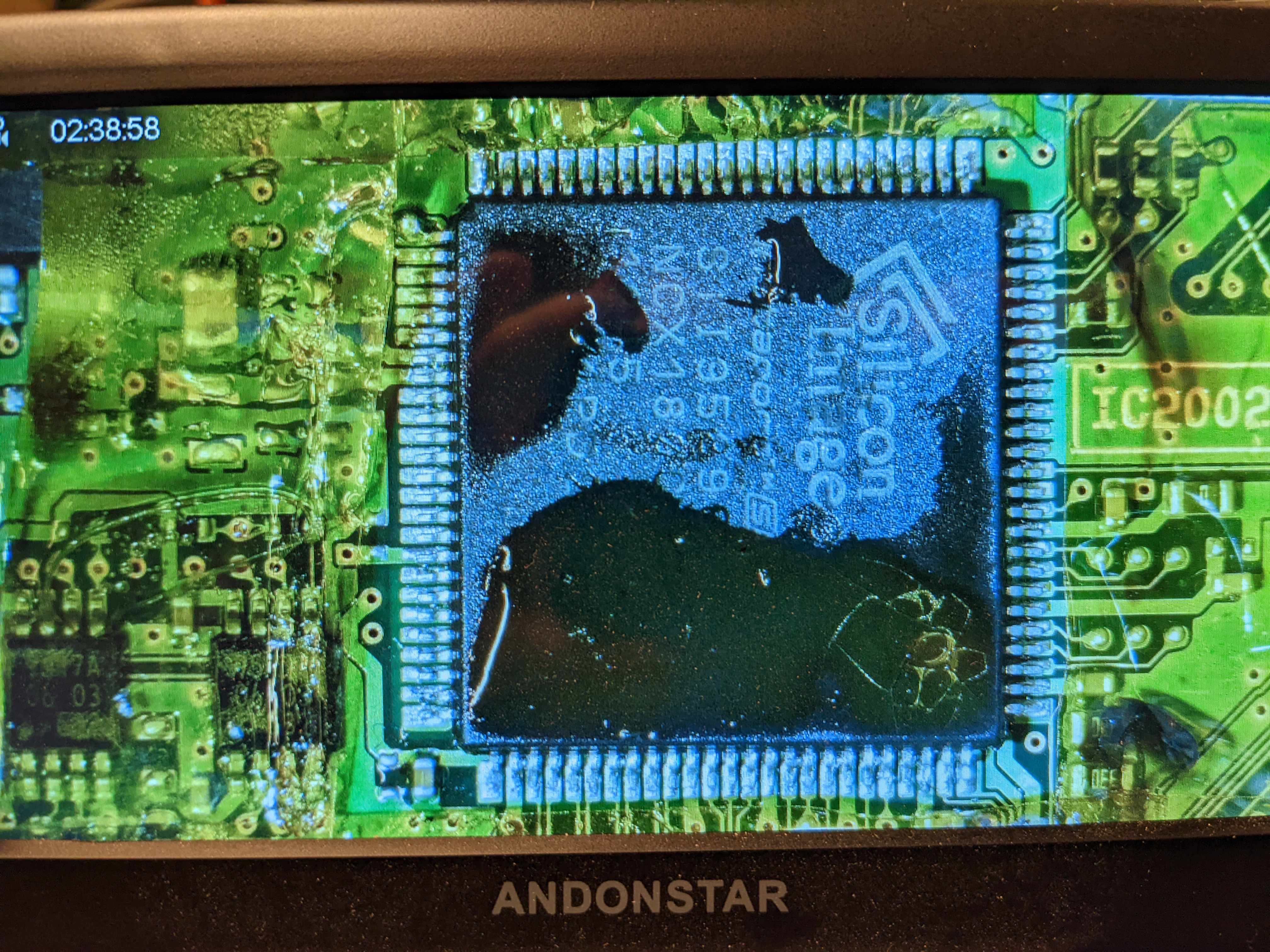
Silicon Image Sil9589CTU0
 Sil9589CTU0 (broken)
In order to determine if it really was the Sil9589CTU0 IC that was broken I carefully lifted pin DSCL4 (see picture below).
After lifting the pin I could confirm that PIN 15 on the HDMI contact was no longer short-circuited to GND.
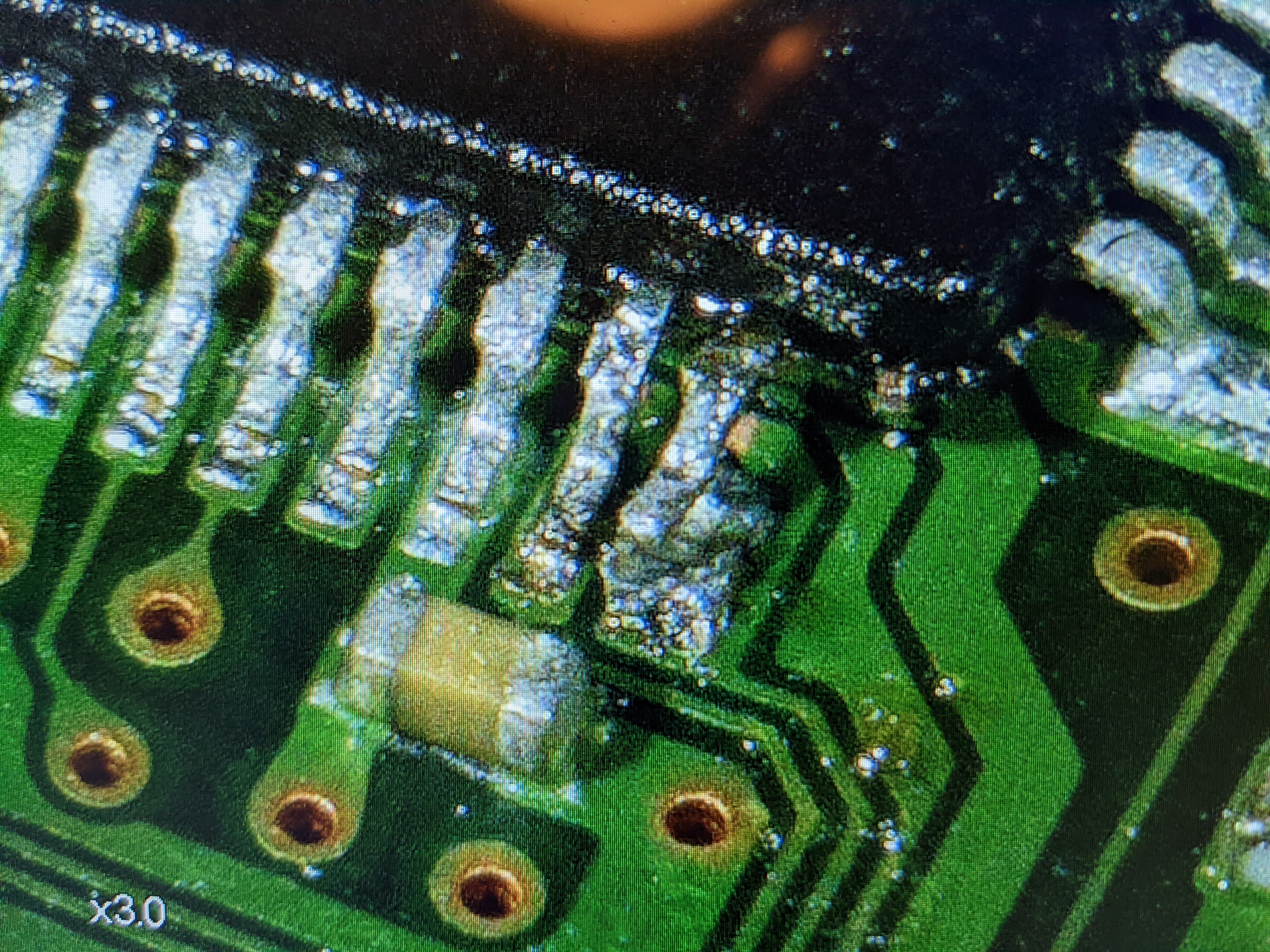 DSCL4 lifted
I then connected the Salea Logic Analyzer to PIN73 (CSCL) and PIN72 (CSDA) in order to see if I could sniff something on the Control I2C bus.
I could see traffic on the bus, but also a lot of NAK´s. It seemed that some other IC on the PCB was trying to talk to Sil9589, but it was not responding.
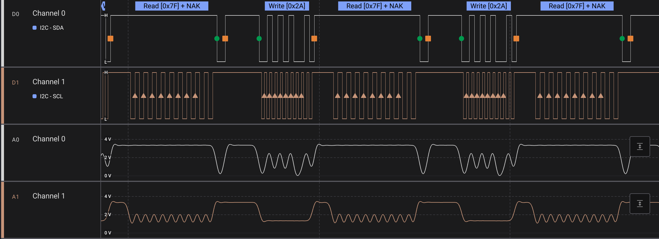 I2C NAK
At this point my best guess was that Sil9589 was broken, and replacing would (hopefully) get HDMI1 working again. Looking at the PCB it seemed that Sil9679 (HDMI2) was connected to Sil9589 (HDMI1), which in return sent the TMDS video signals onwards to the next IC.
Sourcing new IC's
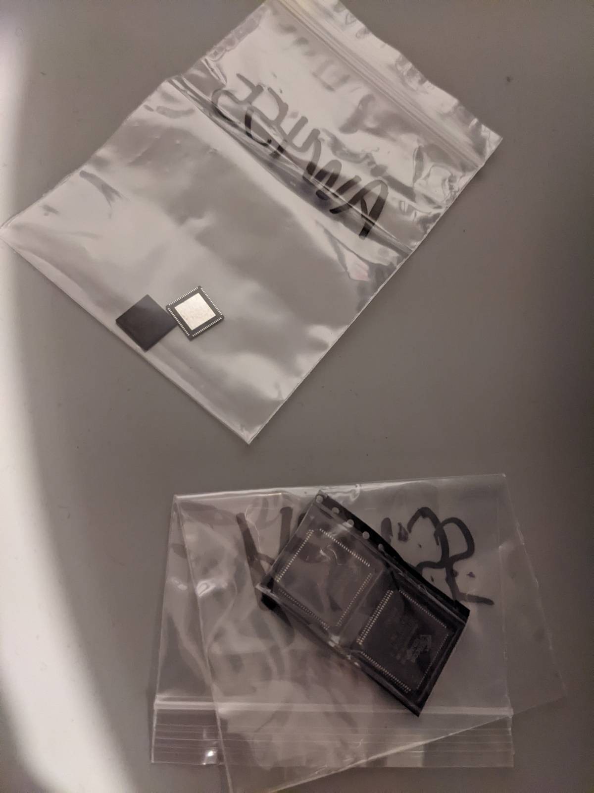
Luckily I could find some Sil9589 and Sil9679 on Ebay, so I ordered a few of each. Later on I found out that it was indeed a good idea to buy a few extras...
After ~1 month I got the IC in the mail. Looking at the IC in detail it was obvious that these IC´s had been used before since a few pins were actually bent. Not the best start...
The plan:
- Desolder broken Sil9589
- Clean PCB
- Solder back a (hopefully) working Sil9589
- Profit!
I had to make a decision regarding how to rework the PCB. Option 1: Disassemble the projector in order to remove the PCB. Option 2: Replace Sil9589 without removing the PCB from the projector.
It would be significantly easier to rework the PCB without having it mounted in the projector. On the other it seemed risky to dissemble the projector since it could mess up alignments in the optical parts.
I decided to go with option 2.
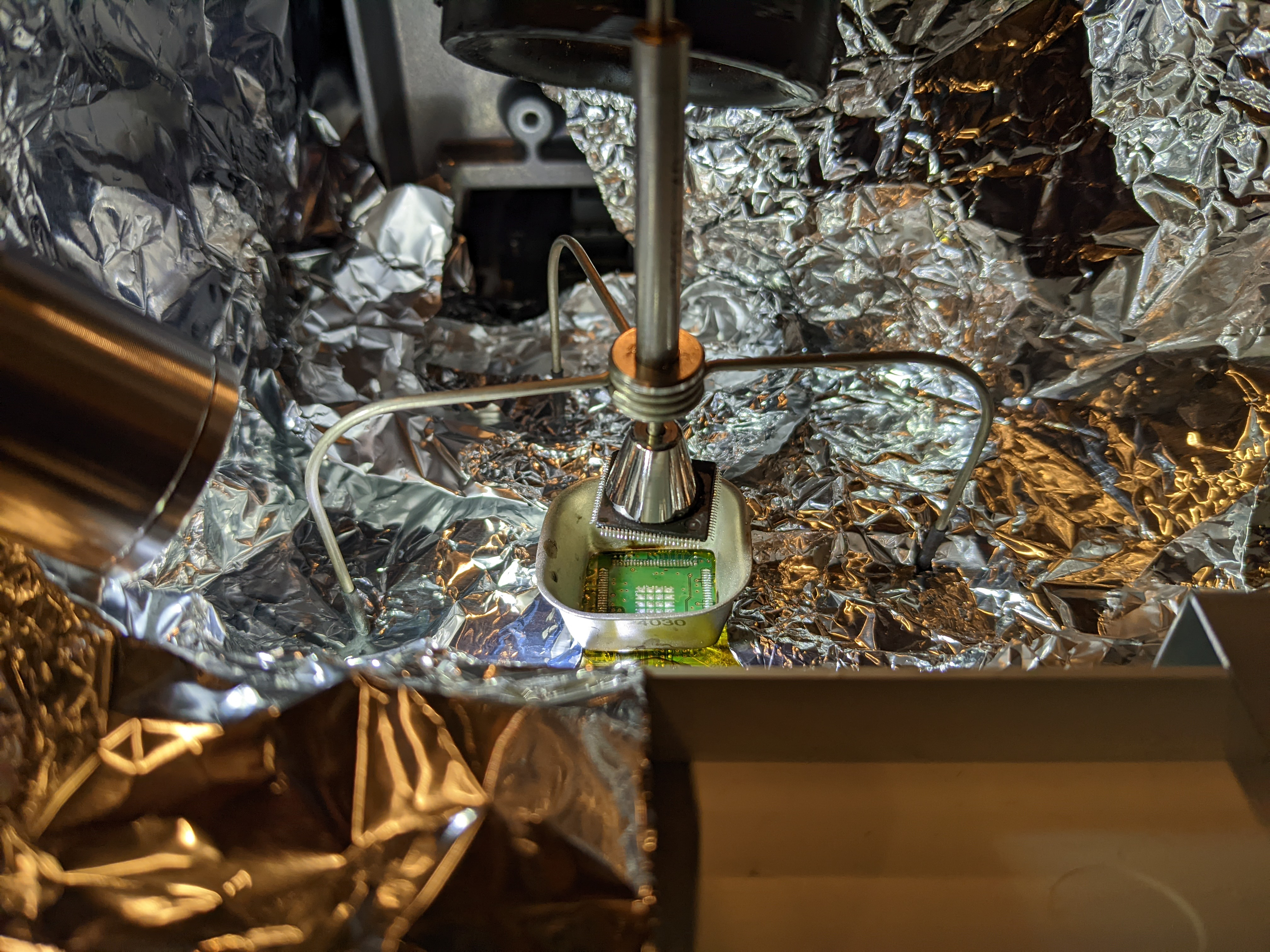
Chip-off
Aluminum foil and kapton tape was used to protect the PCB. Flux was applied on all four sides of the IC. A heat gun was used in combination with the JBC desolder tripod.
It took a fair amount of heat before the chip-off succeeded (450 degrees Celcius). The reason for the time-consuming process was likely the exposed pads (ePad). Since I had no option to pre-heat the PCB it took a while before the heat propagated to the GND plane. Going with option 1 would for sure have made this part easier...
Cleanup
After the chip-off succeeded I cleaned the pads on the PCB using solder wick and flux.
Chip-on
- Solder paste was applied to the ePads (on the PCB). Since I did not have a stencil the solder paste was applied with a "best effort" strategy, hoping that the flux would do is thing once heat was applied.
- Aligning the IC was the most tricky part, especially since the pitch was only 0.5 mm.
- I measured the temperature on the PCB with a temperature probe, in order to not over-heat the PCB/IC.
- The solder paste had a temperature curve included, so I tried to follow that with a "best effort" method. Using a rework station would have been preferable for this step, but since I went with option 2 this was not an option.
Soldering the pins
- After chip-on the IC seemed to be pretty aligned but I had a real hard time to manually solder the 100 pins.
- For some reason the IC was "floating" above the PCB. The 100 pins on the IC was not connected to the pads on the PCB...
 Pins not touching the PCB
 Pin soldering
- As it turned out I had probably not cleaned the ePad area on the PCB enough after the chip-off... Or maybe the solder paste was not fully melted.
- As a workaround I manually bent all the 100 pins, in order for the pins to make contact with the PCB.
- I manually soldered the 100 pins, even though it did not look pretty with all the bent pins...
All good?
- In order to verify that everything was looking alright I measured all the power VDD pins with the multimeter.
- DSCL4 was no longer grounded, a good sign!
Moment of truth
I connected a Chromecast to HDMI #1 and powered up the system. Waiting for a while... No input signal :-( But... I went out of the room for a while and when I came back the projector had restarted, and voilà, there was the Google logo! Not really sure what happened during the reboot, but my educated guess is that the main SoC configured the NVRAM of the Sil9589 using the Control I2C commands, thus the reason why it worked after a reboot.
I spent the next few hours watching movies and I was very happy that I managed to fix the broken HDMI. Went to bed as a happy camper.
And then...
All was well, until.... After a few days I started up the system again, but this time nothing was working....................
At this point I was considering throwing out the projector. I double-checked all connections on the PCB but I could not find anything that was looking strange. I gave up.
Chip-off and chip-on (again)
After a few weeks, maybe months... With new energy I decided to repeat everything AGAIN (since I had a few extra Sil9589). This time I was VERY careful cleaning the ePad area. After chip-on the pins on the IC was touching the PCB as expected, making the manual soldering of the 100 pins a much easier process.
 Second chip-off
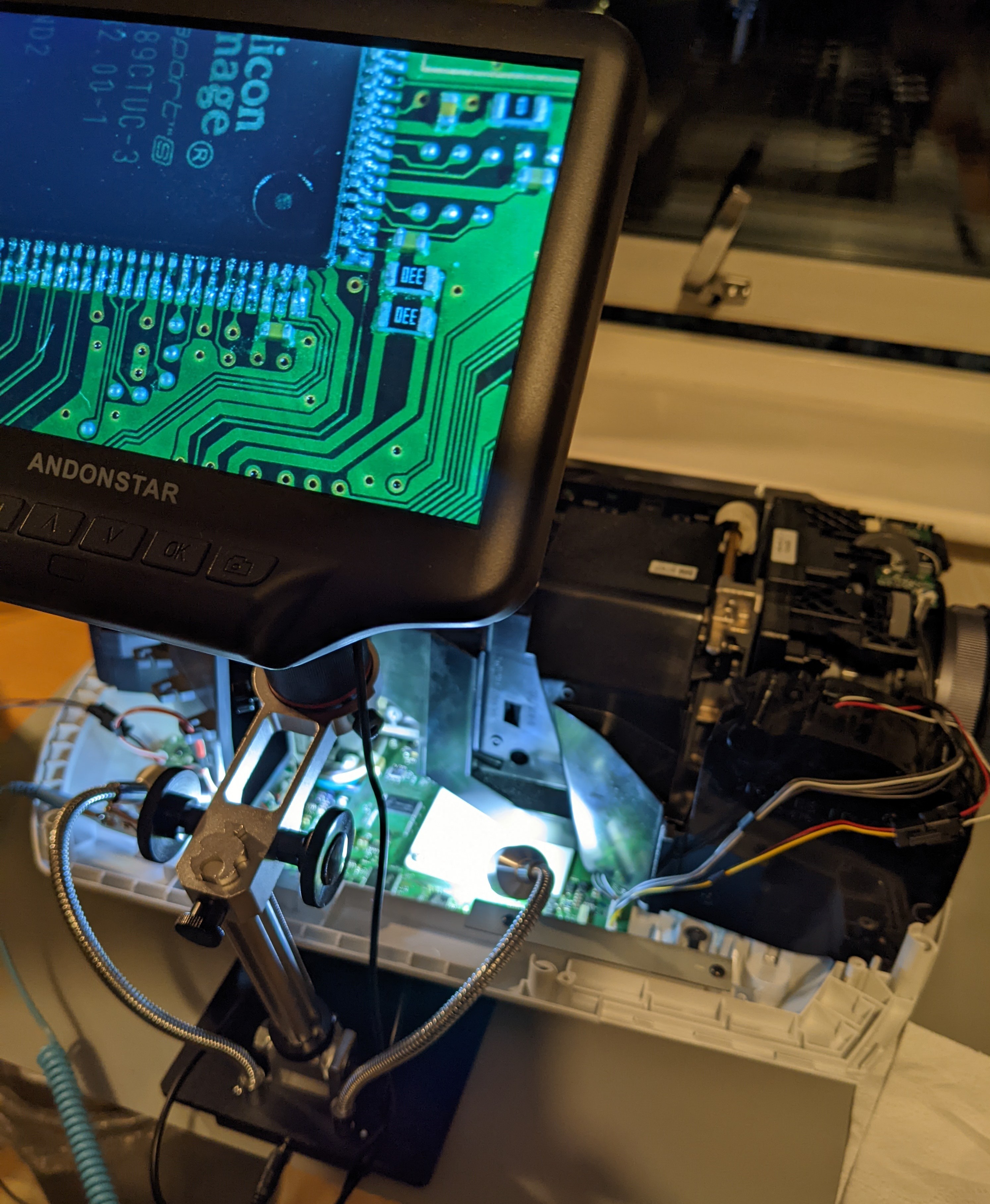
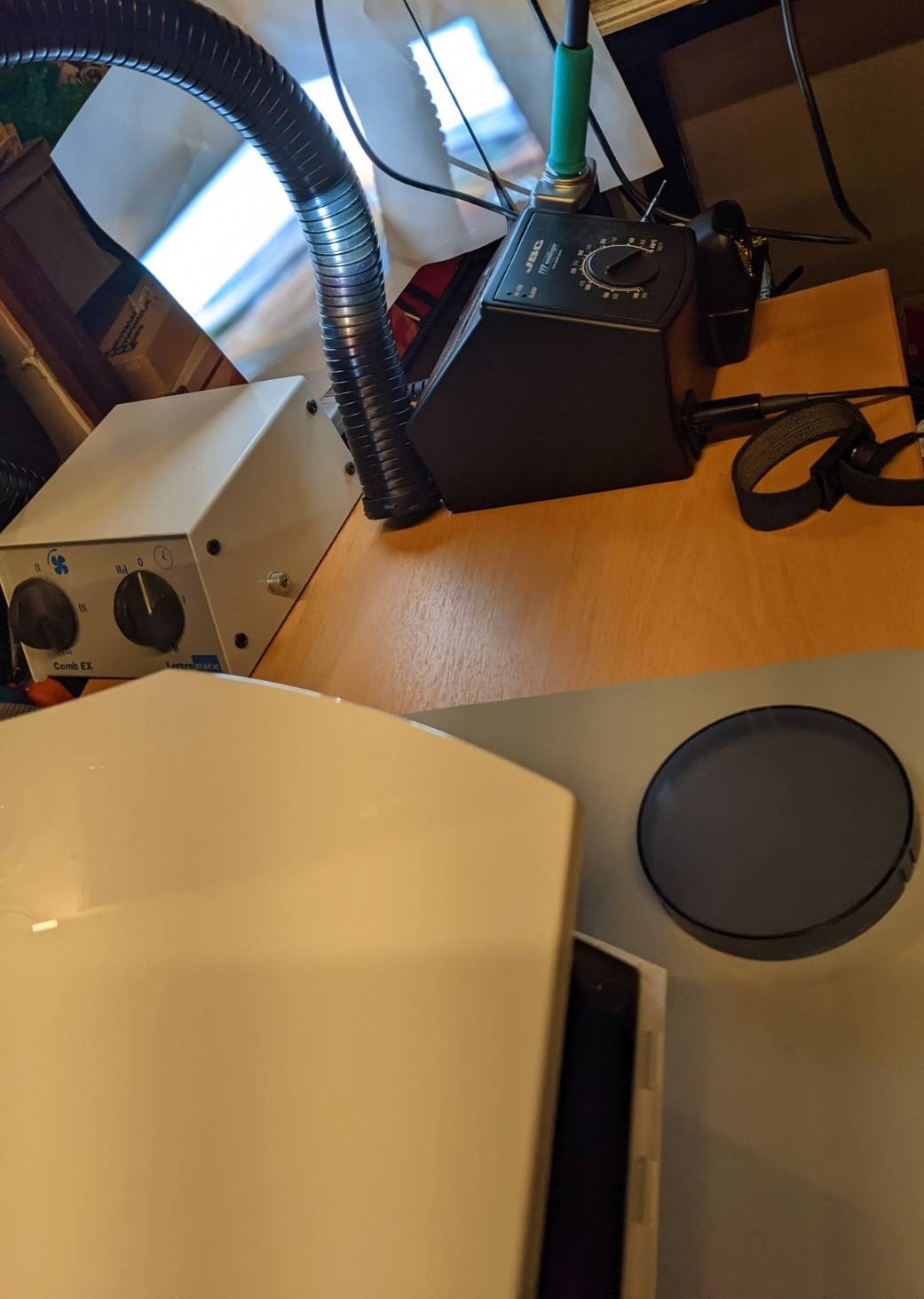
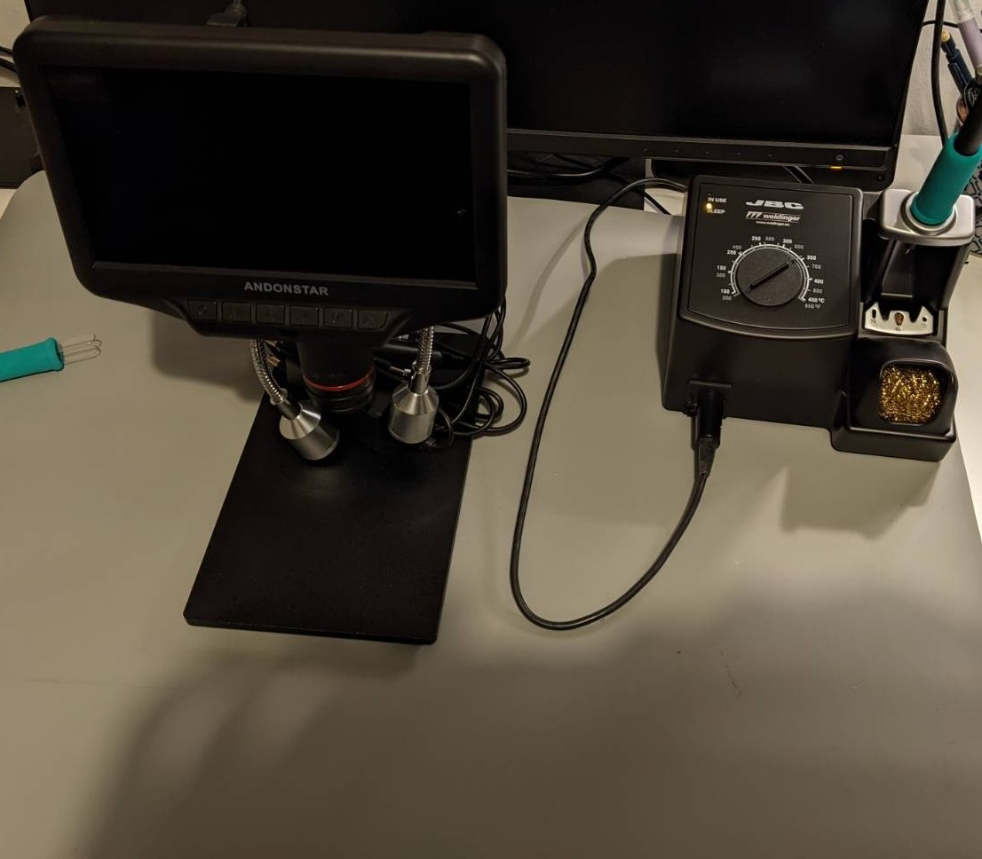
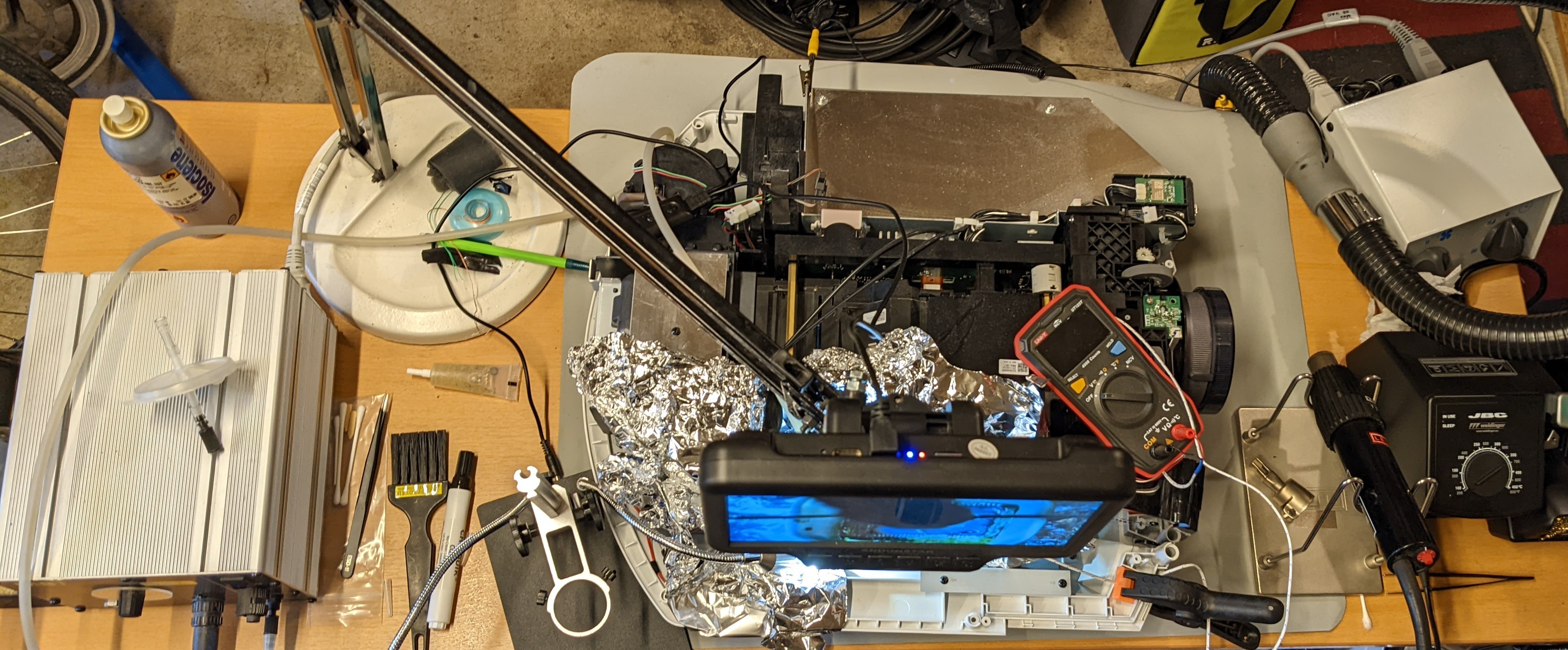 Complete setup for chip-on (microscope mounted on IKEA desk-lamp arm
 Second chip-on
Moment of truth (again)
I booted up the system and it worked on the first try, no reboot required!
Let there be light (and picture)!
This time around I had mounted a temperature sensor on the IC. After 30 minutes the temperature was only 29 degrees Celsius, good enough!
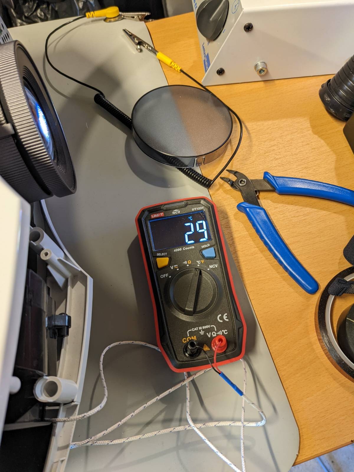 Temperature test
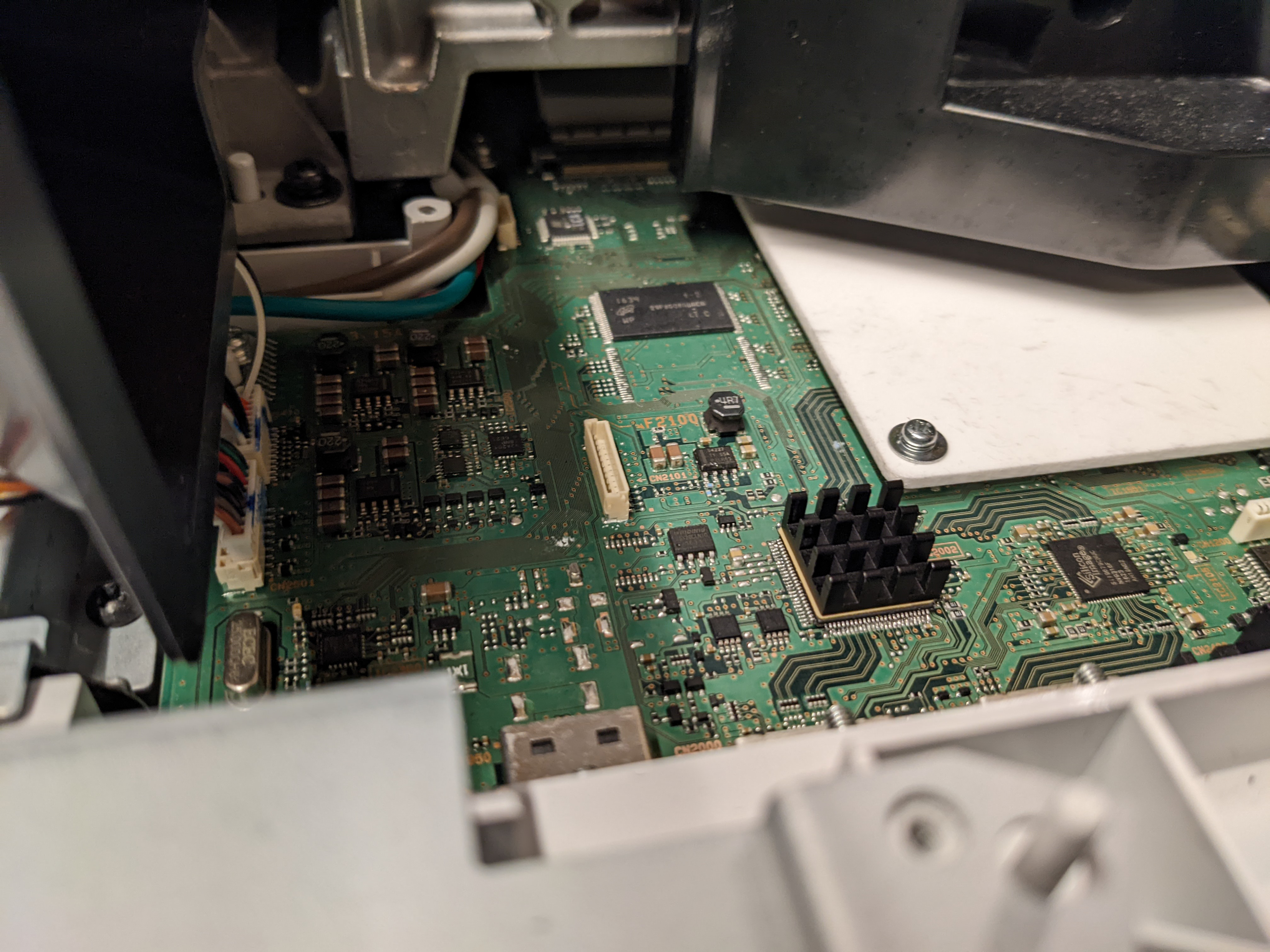
Upgrade
Since I did not know why the IC failed in the first attempt I decided to "upgrade" the IC with a heat sink, in case it was to too much heat that killed it the first time.
Profit?
Fast-forward ~19 months and the projector is still working, mission accomplished!
Fun facts!
- Do not connect the ESD wrist band to HDMI shield... I measured (and felt!) 64 VAC. I was not the first to notice this, see Voltage on HDMI ground
Software
Hardware
-
Hot Air Gun
-
Vaccum Pump
Timeline
-
Nov 2021: Trying to find the service manual. ElektroTanya to the rescue for the older model HW30ES. No luck with HW65ES
-
Dec 2021: Debugging starts...
-
March 2022: First attempt
-
May 2022: Second attempt
-
Dec 2023: Still working!
Credits
- Thanks to Johan L for mental support during this project!